Check out our latest products
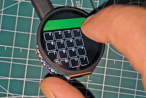
In the previous article of this DIY device series, the smallest touchscreen phone was created using the SIM800L for the 2G cellular network and a round touch display. This design is now finalised by integrating the previously developed user interface (UI) with its core functions and consolidating everything into a single system powered by a real-time operating system (RTOS). The cellular network compatibility is also enhanced by replacing the 2G GSM module with a 4G GSM module, enabling support for LTE and 4G networks (see Fig. 2). Additional applications, such as a calculator and other basic apps, are included. The entire system operates on the RTOS platform. Fig. 1 illustrates the IndusPhone calculator application.


Fig. 2 illustrates the 4G GSM module (left) and MIC (right). The MIC used in this device is an electret microphone capsule, which is commonly used in small electronic devices like mobile phones, hearing aids, and various audio recording devices. These microphones are compact, sensitive, and ideal for small form-factor applications. The tiny holes on top allow sound to enter, where a diaphragm inside the capsule converts sound waves into an electrical signal. The components required to build the IndusPhone are listed in the table above.
| Bill of Materials | ||||||||
| ID | Name | Designator | Footprint | Quantity | Manufacturer Part | Manufacturer | Supplier | Supplier Part |
| 1 | Buzzer | B1 | Buzzer-12mm SMD | 1 | ||||
| 2 | CST816 | CN1 | QFN20-3×3 | 1 | CST816-S | Hynitron Microelectronics | LCSC | |
| 3 | GMI6027P-2C30DB | MIC1 | MIC-TH_BD6.0-P1.90-D0.4-L | 1 | GMI6027P-2C30DB | INGHAi | LCSC | C233898 |
| 4 | ADIA7670C | MOD2 | ADIA7670C | 1 | ADIA7670C | ADIA7670C | Rajguru | ADIA7670C |
| 5 | Speaker | S1 | SMD 3 solder | 1 | ||||
| 6 | GC9A01 | U1 | GC9A01 TFT LCD screen | 1 | GC9A01 | GoldenMorning display | ||
| 7 | IndusBoard | U2 | IndusBoard Coin | 1 | IndusBoard Coin | IndusBoard | IndusBoard | Coin |
| 8 | Antenna | U4 | Antenna | 1 | ||||
Circuit diagram and working
Fig. 3 presents the final circuit diagram for the world’s smallest programmable IndusPhone device. It is built around the 4G GSM module (A7670C), self-capacitance touch chip (CST816), microphone (GMI6027P), SMD speaker, LCD screen (FC9A01), antenna, and display. The entire system is powered by a 3.3V battery. The buzzer will ring when an incoming call is detected and serves as an input to the IndusBoard for interrupts related to the incoming call.

Please register to view this article or log in below. Tip: Please subscribe to EFY Prime to read the Prime articles.


![[5G & 2.4G] Indoor/Outdoor Security Camera for Home, Baby/Elder/Dog/Pet Camera with Phone App, Wi-Fi Camera w/Spotlight, Color Night Vision, 2-Way Audio, 24/7, SD/Cloud Storage, Work w/Alexa, 2Pack](https://m.media-amazon.com/images/I/71gzKbvCrrL._AC_SL1500_.jpg)


![[3 Pack] Sport Bands Compatible with Fitbit Charge 5 Bands Women Men, Adjustable Soft Silicone Charge 5 Wristband Strap for Fitbit Charge 5, Large](https://m.media-amazon.com/images/I/61Tqj4Sz2rL._AC_SL1500_.jpg)
