
Check out our latest products

![[5G & 2.4G] Indoor/Outdoor Security Camera for Home, Baby/Elder/Dog/Pet Camera with Phone App, Wi-Fi Camera w/Spotlight, Color Night Vision, 2-Way Audio, 24/7, SD/Cloud Storage, Work w/Alexa, 2Pack](https://m.media-amazon.com/images/I/71gzKbvCrrL._AC_SL1500_.jpg)


By integrating the OPA2810 and BUF634A, the system ensures accuracy, stability, and wide impedance coverage, making it a reliable choice for semiconductor testing, digital multimeters, and vector network analyzers.
The objective of any test and measurement system is to measure a device under test (DUT) with minimal complexity while ensuring that introduced errors remain significantly smaller than those present in the DUT. For impedance measurements, multiple techniques exist, each offering tradeoffs between measurement accuracy, complexity, and frequency range.
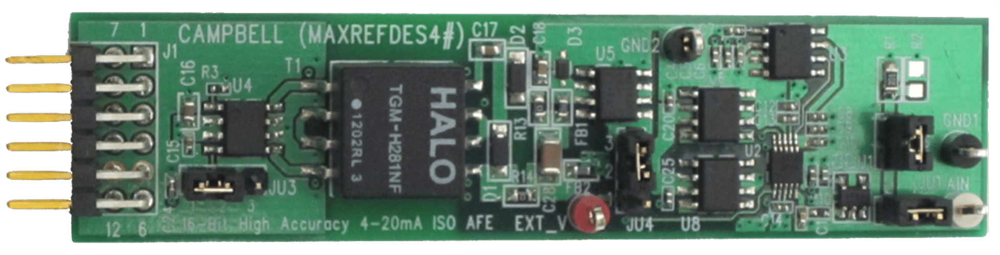
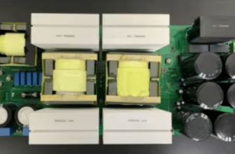
This reference design, TIDA-060029 by Texas Instruments employs an auto-balancing impedance measurement method, chosen for its excellent accuracy over a broad impedance range without requiring manual tuning. Auto-balancing impedance measurement circuits can be difficult to stabilize since their stability depends on both the component type and value. Therefore, an inherently stable circuit is necessary, regardless of the measured component’s characteristics. This design presents a robust analog signal-chain solution with 0.1% accuracy, making it ideal for LCR meter applications. It measures inductance (L), capacitance (C), and resistance (R) across a wide impedance range from 1 Ω to 10 MΩ, operates at frequencies up to 100 kHz, and has been tested at 100 Hz, 1 kHz, 10 kHz, and 100 kHz. The circuit is inherently stable, ensuring precise and consistent impedance measurements.

This reference design is well-suited for applications such as digital multimeters (DMMs), impedance and vector network analyzers, and semiconductor manufacturing and testing. A key component in this design is the OPA2810, a dual-channel, FET-input voltage-feedback operational amplifier with an extremely low input bias current of 2 pA, which is critical for high-impedance measurements up to 10 MΩ. The OPA2810 is unity-gain stable, featuring a 105 MHz small-signal bandwidth, 120 dB open-loop gain (Aol), and maintaining over 60 dB at frequencies below 100 kHz. Its gain-bandwidth product (GBW) of 70 MHz ensures accurate signal processing, while the ±13.5 V supply voltage optimizes distortion performance. Additionally, its low voltage noise (6 nV/√Hz) minimizes signal degradation, further enhancing measurement accuracy. A high Aol value ensures that the inverting input voltage remains close to zero, reducing measurement errors and making the OPA2810 a crucial component in this impedance measurement system.
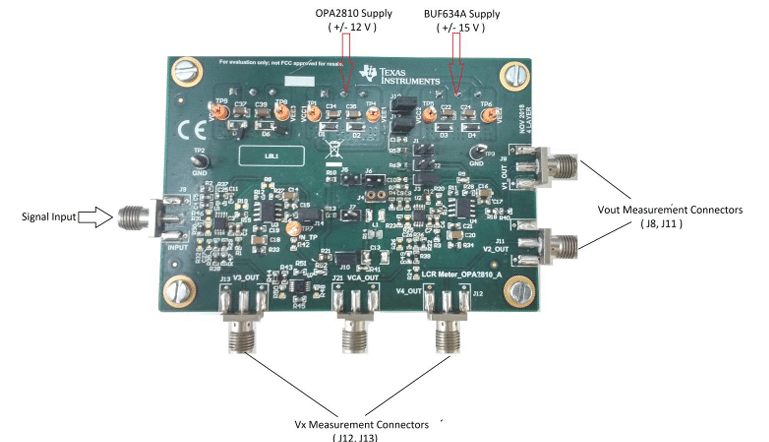
The BUF634A, a high-speed, wide-bandwidth unity-gain buffer, is optionally used in a composite loop with the OPA2810 to increase the output current capability from 100 mA to 250 mA. It provides two selectable bandwidth options, 35 MHz (low bandwidth) and 210 MHz (high bandwidth), offering flexibility based on application requirements. Although not mandatory, the BUF634A enhances the circuit’s drive capability, making it useful in scenarios where higher current output is needed. This reference design effectively demonstrates a high-precision auto-balancing impedance measurement solution for LCR meters.

TI has tested this reference design. It comes with a bill of materials (BOM), schematics, assembly drawing, printed circuit board (PCB) layout, and more. The company’s website has additional data about the reference design. To read more about this reference design, click here.

![[3 Pack] Sport Bands Compatible with Fitbit Charge 5 Bands Women Men, Adjustable Soft Silicone Charge 5 Wristband Strap for Fitbit Charge 5, Large](https://m.media-amazon.com/images/I/61Tqj4Sz2rL._AC_SL1500_.jpg)