
Check out our latest products

![[5G & 2.4G] Indoor/Outdoor Security Camera for Home, Baby/Elder/Dog/Pet Camera with Phone App, Wi-Fi Camera w/Spotlight, Color Night Vision, 2-Way Audio, 24/7, SD/Cloud Storage, Work w/Alexa, 2Pack](https://m.media-amazon.com/images/I/71gzKbvCrrL._AC_SL1500_.jpg)


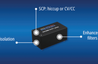
The 400-W design changes 36–60 V to 12 V. It saves power, works in cars, keeps output safe and steady.
TIDA-01407 is a reference design from Texas Instruments (TI). It is a 400-W automotive phase-shifted full-bridge converter. It supports a DC input range of 36 V to 60 V and provides a 12-V output. The phase-shifted controller includes programmable delays to maintain zero voltage switching (ZVS) across different conditions.
The output uses synchronous rectification for fast response and wide loop bandwidth. It can regulate 12 V at no load with standby power under 100 mW. A transformer provides isolation to prevent shorting between the 48-V battery and the output. The half-bridge gate drivers can handle up to 120 V DC boot voltage. This design is used in automotive systems such as HEV/EV traction inverters, double-clutch transmissions, control units, and HEV/EV DC-DC converters.

This reference design is used in mild hybrid electric vehicles (MHEVs). The power supply uses a controller, which allows programmable delays. This helps achieve ZVS across different working conditions. On the output side, synchronous rectifiers are used. These support a fast response to load changes and allow wide loop bandwidth.
The system can keep the 12 V output steady even with no load, using under 100 milliwatts of standby power. A transformer provides isolation—so if the MOSFETs fail, the 48 V does not reach the output load.

The primary side uses half-bridge gate drivers to control both high and low side MOSFETs. These drivers can handle up to 120 V of boot voltage. The output voltage is regulated through the transformer’s primary side, removing the need for an optocoupler. This helps reduce board size and improve reliability.
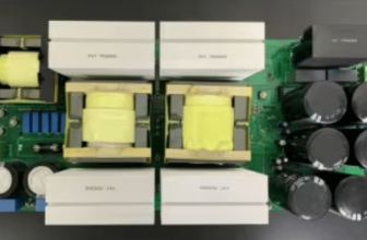
The design includes three main parts that work together to manage power conversion. The first part is current sensing on the primary side, which uses a current transformer. This provides cycle-by-cycle overcurrent protection and helps with delay control to keep the system stable.
The second part is the power stage of the phase-shifted full-bridge on the primary side. This stage uses zero-voltage switching and has power-saving modes that adjust based on the load. These features help improve efficiency across different load levels. The design can also handle automotive conditions, such as changes in voltage from cold starts or load dumps, which can go up to 80 V and scale to 100 V.
The third part is the use of synchronous rectification MOSFETs on the secondary side. These reduce the voltage drop across the MOSFETs. They also reduce spikes or dips caused by load changes. They allow fast response and wide loop bandwidth under changing conditions.
TI has tested this reference design. It comes with a bill of materials (BOM), schematics, assembly drawing, printed circuit board (PCB) layout, and more. The company’s website has additional data about the reference design. To read more about this reference design, click here.

![[3 Pack] Sport Bands Compatible with Fitbit Charge 5 Bands Women Men, Adjustable Soft Silicone Charge 5 Wristband Strap for Fitbit Charge 5, Large](https://m.media-amazon.com/images/I/61Tqj4Sz2rL._AC_SL1500_.jpg)