
Check out our latest products

![[5G & 2.4G] Indoor/Outdoor Security Camera for Home, Baby/Elder/Dog/Pet Camera with Phone App, Wi-Fi Camera w/Spotlight, Color Night Vision, 2-Way Audio, 24/7, SD/Cloud Storage, Work w/Alexa, 2Pack](https://m.media-amazon.com/images/I/71gzKbvCrrL._AC_SL1500_.jpg)


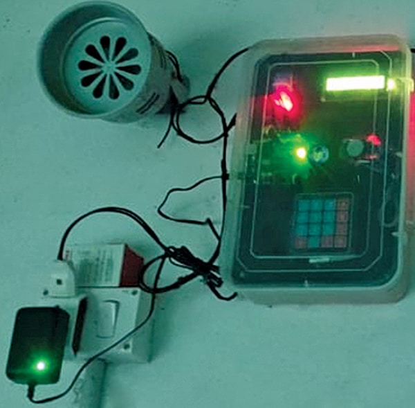
This proposed Arduino-based automatic bell device is an electronic system that rings bells at predefined times without manual intervention.
It is built around an Arduino Uno, which is programmed to control a buzzer or electric bell based on a preset schedule, eliminating the need for manual ringing.
An RTC (real-time clock) module ensures precise timekeeping, allowing administrators to set and adjust bell timings as required. An LCD can be added to show the current time and upcoming bell schedules. This system improves efficiency, maintains a disciplined routine, and removes dependency on manual operation.

Table 1 lists the components required to build this device, while Fig. 1 shows the authors’ prototype.
| Table 1: Bill of Materials | |
| Components | Quantity |
| Arduino Uno R3 (MOD1) | 1 |
| DS3231 RTC | 1 |
| 16×2 LCD display with I2C (MOD2) | 1 |
| 4×4 matrix keypad | 1 |
| 5V SPDT relay | 1 |
| 9V, 1A adaptor for power supply to the Arduino board | 1 |
| 230V AC call bell | 1 |
| Buzzer | 1 |
| Jumper wires and other wires | As required |
Circuit and Working
Fig. 2 shows the circuit diagram of the automatic school bell. It is built around Arduino Uno R3, 16×2 LCD display with I2C (MOD1), DS3231 RTC, 4×4 matrix keypad, 5V SPDT relay, 230V AC call bell, and a few other essential components. A 9V, 1A adaptor is used to supply power to the Arduino Uno after uploading the source code.

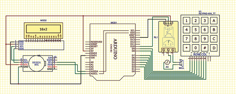
The system features a built-in real-time clock (DS3231), which tracks real-time data. When the current time matches the preset bell ringing time, the relay energises and switches on the bell. The bell timings can be modified at any time using the 4×4 keypad, making it adaptable for regular school schedules as well as examination periods.
The real-time clock is displayed on a 16×2 LCD, providing a clear view of the day, date, and time. The Arduino Uno controls all functions, receiving input via the keypad and storing it in its EEPROM memory. When the stored bell time matches the real-time clock, the bell rings for a predetermined duration, which is set to approximately ten seconds in this implementation.
Software
This system requires libraries for the DS3231 RTC and I2C-based LCD, which need to be installed in Arduino IDE. To install these libraries:
Open Arduino IDE.
Navigate to sketch→Include library→Manage libraries.
Search for and install the following libraries:
- DS3231
- LiquidCrystal_I2C
- Keypad
After installing the required libraries, download the source code from electronicsforu.com. Upload the code by selecting:
Board: Arduino Uno
COM Port: The port where the Arduino is connected
If all libraries (keypad, LCD display, and DS3231 RTC) are correctly installed, the code will upload successfully. Fig. 3 shows a snippet of the source code.
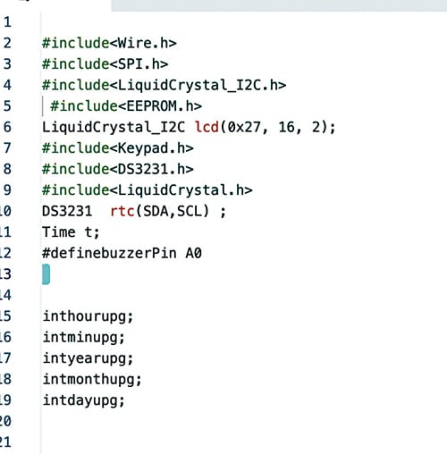
Next, the loop function is created to update the time from the RTC module, accept keypad inputs for setting bell timings and dates, and display the same on the LCD. All settings are saved in EEPROM, ensuring they remain intact even after power is turned off.
Recommended: Arduino Projects
Construction and Setup
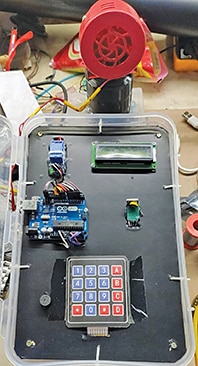
After uploading the source code into the Arduino Uno, assemble the circuit using Tables 2, 3, 4, 5, and 6 and the circuit diagram shown in Fig. 4. Enclose the entire setup in a small plastic box. Refer to Fig. 4 before assembling the prototype for a better understanding of the final build.
| Table 2: 4×4 Matrix keypad connections | |
| 4×4 Keypad Pin | Arduino Uno Pin |
| Row pin 0 | D9 |
| Row pin 1 | D8 |
| Row pin 2 | D7 |
| Row pin 3 | D6 |
| Col pin 0 | D5 |
| Col pin 1 | D4 |
| Col pin 2 | D3 |
| Col pin 3 | D2 |
| Table 3: DS3231 connections with Uno | |
| DS3231 Pins | Arduino Uno Pin |
| VCC | 5V |
| GND | GND |
| SDA | A4 |
| SCL | A5 |
| Table 4 16×2 LCD connections with Arduino Uno | |
| 12C LCD Pins | Arduino Uno Pin |
| VCC | 5V |
| GND | GND |
| SDA | SDA |
| SCL | SCL |
| Table 5: Relay connections with Arduino Uno | |
| Relay Pins | Arduino Pins |
| VCC | 5V |
| GND | GND |
| IN | D10 |
| Table 6: Buzzer with Uno | |
| Buzzer Pin | Arduino Uno |
| Buzzer positive | A0 |
| Buzzer negative | GND |
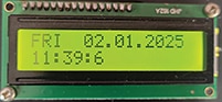
Power on the assembled unit by connecting the 9V adaptor to the Arduino Uno. The default day, date, and time will be displayed (see Fig. 5). Press ‘*’ on the keypad to modify the settings.
Two options will appear:
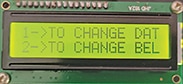
Option 1: Change day, date, and time
Option 2: Set bell timings (see Fig. 6). If you want to change, press the ‘*’ key using the keypad.
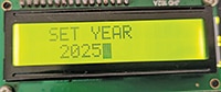
Press ‘1’ to select ‘SET YEAR’. Use the keypad to enter the year, then press ‘#’ (see Fig. 7).
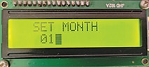
Press ‘#’ to proceed to ‘SET MONTH’. Enter the month using the keypad, then press ‘#’ (see Fig. 8).
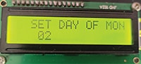
Press ‘#’ to access ‘SET DAY OF THE MONTH’. Use the keypad to enter the day (1-31), then press ‘#’ (see Fig. 9).
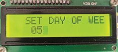
Press ‘#’ to move to ‘SET DAY OF THE WEEK’. Enter the corresponding number for the day (MON-1, TUE-2, WED-3, THU-4, FRI-5, SAT-6, SUN-7), then press ‘#’ (see Fig. 10).
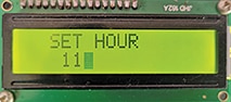
Press ‘#’ to access ‘SET HOUR’. Use the keypad to enter the hour (0-24), then press ‘#’ (see Fig. 11).
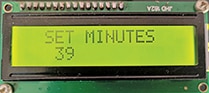
Press ‘#’ to proceed to ‘SET MINUTES’. Enter the minutes (0-60) using the keypad, then press ‘#’ (see Fig. 12).
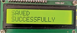
Once all details are set, the system updates and saves the settings (see Fig. 13).
Setting Bell Timings
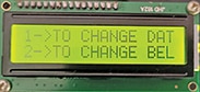
Power on the system. The default day, date, and time will be displayed (see Fig. 14). Press ‘*’ on the keypad to modify the settings. Two options will appear.

Select option 2: Set Bell Timings (see Fig. 15).
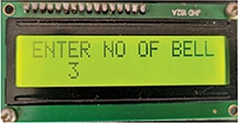
Enter the number of bells required (e.g., 3, 7, 10, or more) and confirm by pressing ‘#’ (see Fig. 16).
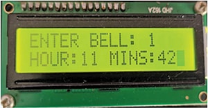
Set individual bell timings (hour and minutes) one by one (see Fig. 17).
To review the saved bell timings, press ‘C’ repeatedly to cycle through the stored times.
Once the settings are complete, the prototype is ready for use.
K. Muni Sekhar Reddy is a lecturer at ECE Department at the Government Polytechnic, Kamalapuram, Andhra Pradesh
Chadipiralla Sivakavitha is a technology enthusiast studying at ECE Department of the Government Polytechnic, Kamalapuram, Andhra Pradesh

![[3 Pack] Sport Bands Compatible with Fitbit Charge 5 Bands Women Men, Adjustable Soft Silicone Charge 5 Wristband Strap for Fitbit Charge 5, Large](https://m.media-amazon.com/images/I/61Tqj4Sz2rL._AC_SL1500_.jpg)