
Check out our latest products

![[5G & 2.4G] Indoor/Outdoor Security Camera for Home, Baby/Elder/Dog/Pet Camera with Phone App, Wi-Fi Camera w/Spotlight, Color Night Vision, 2-Way Audio, 24/7, SD/Cloud Storage, Work w/Alexa, 2Pack](https://m.media-amazon.com/images/I/71gzKbvCrrL._AC_SL1500_.jpg)


Water storage often presents challenges such as monitoring tank levels, preventing overflow, and reducing manual intervention to operate the pump. Two types of devices, known as water level indicators and controllers, have been developed to address these issues.
These devices have key drawbacks. Water level indicators require manual pump operation and often waste power as multiple LEDs stay unnecessarily lit. Water level controllers face frequent pump cycling from minor fluctuations, accelerating the pump’s wear and tear and shortening its lifespan.
Also, Check the Water Pump Controller project that we built previously.

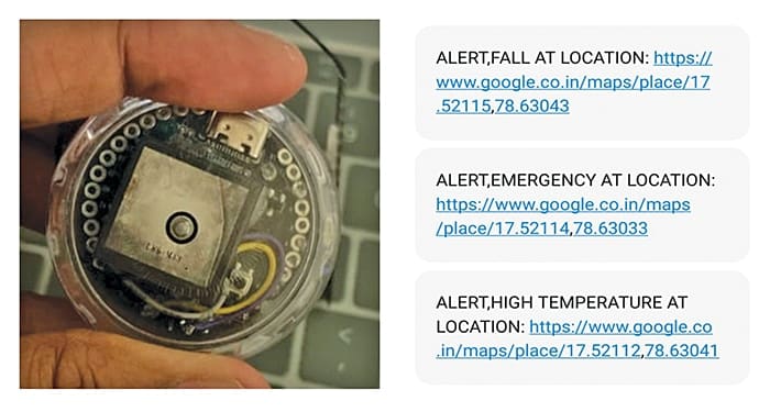
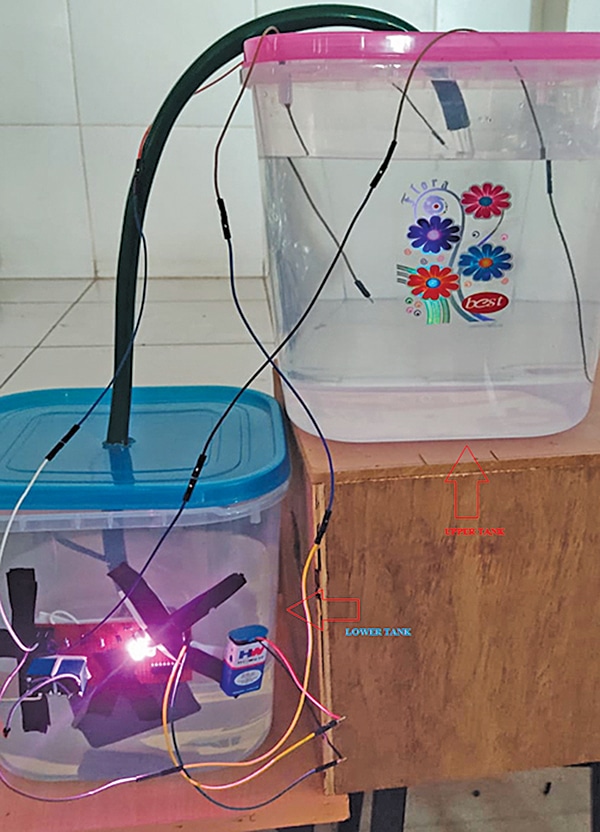
An automatic water level indicator cum controller device can address these problems. To build this device, the components listed in Table 1 are required. Fig. 1 shows the author’s prototype.
| Table 1: List of components | |
| Item | Quantity |
| Arduino Uno (MOD1) | 1 |
| Water level sensors or float switch | 3 |
| 5V SPDT relay (RL1) | 1 |
| BC547 NPN transistor (T1) | 1 |
| 1N4007 rectifier diode (D1) | 1 |
| 330Ω resistor (R1, R2, R3) | 3 |
| 10kΩ resistor (R4, R5, R6) | 3 |
| 1kΩ resistor (R7) | 1 |
| Water pump | 1 |
| 5mm LED | 3 |
| Power supply for Arduino Uno | 5V |
| Power supply for water pump motor | 230V AC |
Arduino Code for Water Level Indicator and Controller
The code is written in Arduino IDE. First, the IDE must be installed. The code can then be downloaded and opened in Arduino IDE.

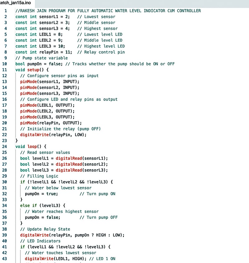
In the initial part of the code, sensor wires, LEDs, and the relay pin are defined. In the setup function, the pin modes are configured as input for the sensor wires and output for the LEDs and relay.
In the loop function, the levels are detected using the read function. Based on the detected level, the relay turns on or off, controlling the motor connected to it.
The board and port for the Arduino Uno should be selected. The Arduino Uno should then be plugged in, and the source code uploaded. Fig. 2 shows a snippet of the source code.
Circuit
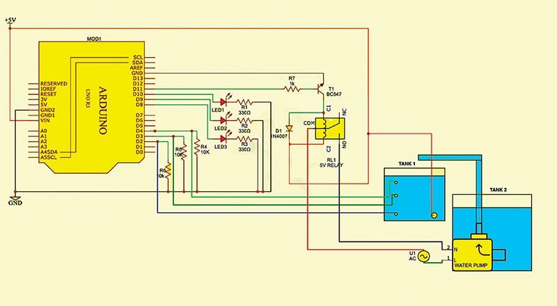
Fig. 3 shows the circuit diagram of the automatic water level indicator cum controller. It is built around an Arduino Uno board (MOD1), three LEDs, a 5V SPDT relay, and other components.
First, all sensors should be installed in the upper tank, and the pump motor should be installed in the lower tank.
The circuit can use either wires as sensors or float switches.
Working
Filling Mode
During water filling, the three wire sensors are positioned at different heights in the tank. The pump motor starts automatically when water is below the lowest sensor.
When water touches the lowest sensor, LED1 lights up, but the pump remains on. When water touches the middle sensor, LED1 turns off, LED2 lights up, and the pump remains on.
When water touches the highest sensor, LED3 lights up, LEDs 1 and 2 turn off, and the pump switches off.
| Table 2: Filling mode | |||||
| Sensor Position | Condition | LED1 | LED2 | LED3 | PUMP |
| Water touches no sensors (below lowest sensor) | Tank is empty | OFF | OFF | OFF | ON |
| Water touches the lowest sensor | Tank is not empty | ON | OFF | OFF | ON |
| Water touches the middle sensor | Tank is partially filled | OFF | ON | OFF | ON |
| Water touches the highest sensor | Tank is full | OFF | OFF | ON | OFF |
Draining Mode
During water drainage, when the water level drops below the highest sensor, LED3 turns off, and LED2 lights up, but the pump remains off.
When the water level reaches below the middle sensor, LED2 turns off, and LED1 lights up, but the pump remains off.
When the water is below the lowest sensor, all LEDs turn off, and the pump starts.
| Table 3: Draining mode | |||||
| Sensor Position | Condition | LED1 | LED2 | LED3 | PUMP |
| Water level is at the highest sensor | Tank is full | OFF | OFF | ON | OFF |
| Water level is below the highest sensor | Tank is partially filled | OFF | ON | OFF | OFF |
| Water level is below the middle sensor | Tank is not empty | ON | OFF | OFF | OFF |
| Water level is below the lowest sensor | Tank is empty | OFF | OFF | OFF | ON |
Testing
The source code must first be uploaded into the Arduino Uno. The components should then be connected as per the circuit diagram shown in Fig. 3. The Arduino Uno board should be powered using a 5V adaptor or a USB cable connected to a laptop or desktop.
The water pump should be connected to a 230V AC power supply through the relay contacts. After powering the device and installing the sensors in the tank, water should be filled into the tank. The LEDs will glow according to the water level, and the pump will switch on or off as described in Tables 2 and 3.
Check other Arduino Projects
Rakesh Jain, Assistant Professor in the ECE Department at Geetanjali Institute of Technical Studies, Udaipur, holds a master’s degree in VLSI, a BE degree in electronics and communication and a diploma in electronics. His research areas are sensors and microcontrollers, and he has 31 copyrights, 9 design patent registrations, and 3 Indian utility patents to his credit. He is the recipient of the Mewar Scientist Award 2023.

![[3 Pack] Sport Bands Compatible with Fitbit Charge 5 Bands Women Men, Adjustable Soft Silicone Charge 5 Wristband Strap for Fitbit Charge 5, Large](https://m.media-amazon.com/images/I/61Tqj4Sz2rL._AC_SL1500_.jpg)