![DIY Blind Stick [Without Code]](https://urbaneleganthomes.com/wp-content/uploads/2025/05/DIY-Blind-Stick-Without-Code.jpg "DIY Blind Stick [Without Code]")
Check out our latest products

![[5G & 2.4G] Indoor/Outdoor Security Camera for Home, Baby/Elder/Dog/Pet Camera with Phone App, Wi-Fi Camera w/Spotlight, Color Night Vision, 2-Way Audio, 24/7, SD/Cloud Storage, Work w/Alexa, 2Pack](https://m.media-amazon.com/images/I/71gzKbvCrrL._AC_SL1500_.jpg)


A stick for the blind proposed here is an assistive device that helps visually impaired individuals navigate safely. It features an infrared (IR) sensor that detects obstacles and activates a buzzer to alert the user. A 9V battery powers the circuit for convenient operation.
Lightweight and portable, the stick enhances mobility by providing real-time feedback on surroundings. It integrates an IR sensor module, a PNP transistor, and a piezo buzzer to detect obstacles and issue audible alerts. Compact yet highly effective, the circuit improves safety for visually impaired individuals.
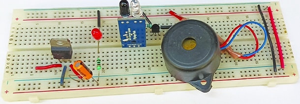
The IR sensor module operates by emitting and receiving infrared signals. When it detects an obstacle, the transistor amplifies the signal, triggering the buzzer. This precise and efficient system enhances user confidence and independence. Fig. 1 shows the author’s prototype.

| Parts List |
| Semiconductors: IC1 – LM7805, 5V voltage regulator T1 – BC558 PNP transistor LED1 – 5mm LED Resistors (all 1/4-watt, ±5% carbon): Capacitors: Miscellaneous: |
Blind Stick Circuit and Working
Fig. 2 shows the circuit diagram of the stick for the blind. It is built around an IR sensor module connected across CON2, a PNP transistor BC558 (T1), a buzzer (PZ1), and a few other components. A 9V battery is sufficient to power the circuit.
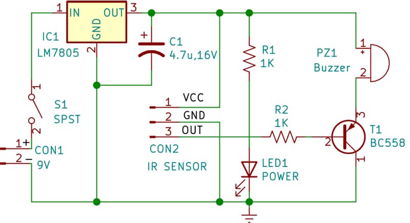
The 9V battery is connected across CON1. A voltage regulator LM7805, reduces the 9V to 5V to power the circuit, as the IR module operates at around 5V. Switch S1 is used to turn on the circuit, and when LED1 lights up, it indicates that the circuit is ready for use.
– Advertisement –
The heart of the circuit is the IR module, which detects objects within a specific distance. The module is fitted at the bottom of the stick. When an obstacle is detected, the stick signals the user by producing a sound through the buzzer.
An IR module can transmit and receive infrared data. In other words, it houses an IR transmitter and a receiver in a single unit with shared circuitry. The IR sensor module has three pins—VCC, GND, and OUT—as shown in Fig. 3. The white LED in the IR module acts as a transmitter, while the black LED (photodiode) is a receiver. The IR transmitter continuously emits infrared light, and the IR receiver checks for reflected light.
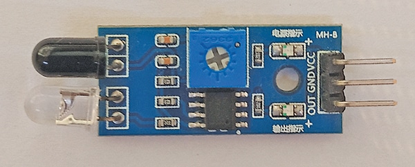
If the light reflects off an object in front, the IR receiver detects it, allowing the IR sensor module to identify the object. The module has an inbuilt potentiometer to adjust the range. It also features two inbuilt SMD LEDs—one for power, which remains on during operation, and another for signal detection, which turns on when an object is detected. Fig. 3 shows an image of the IR sensor module.
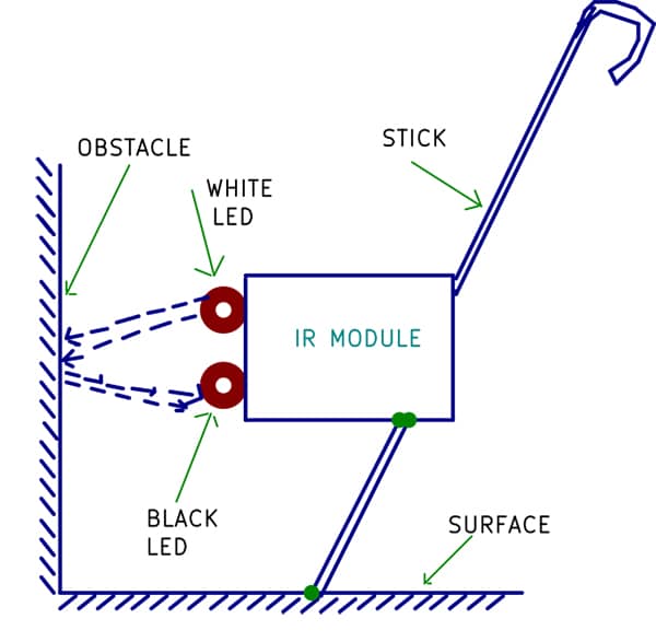
The working of the circuit is quite simple. When the lower section of the stick (where the sensor is fitted) approaches an obstacle, IR rays are reflected, causing the IR module to generate a low signal at its data pin. This activates transistor T1, triggering the buzzer to sound and alerting the user to an obstacle ahead, prompting the person to change direction.
In summary, the circuit instantly detects obstacles via the IR module, and the user receives an audible alert from the buzzer. This helps a user to avoid obstacles safely without collisions.
PCB Design
A full-size, single-sided PCB layout for the blind stick circuit is shown in Fig. 4, with the component layout in Fig. 5. After assembling the circuit on the PCB, enclose it in a suitable cabinet with a window for the IR sensor module.
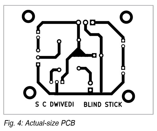

Alternatively, the circuit can be assembled on a general-purpose PCB and enclosed in a plastic box, ensuring that both the IR transmitter and receiver LEDs are positioned outside the box.
Blind Stick Project Installation Steps
Installing a PCB on a walking stick for the visually impaired with an IR sensor is a precise task, requiring a step-by-step approach. Before installation, refer to Fig. 6.
Take the assembled PCB.
Identify a position near the bottom of the stick where the sensor can detect obstacles.
Fix the IR module with its enclosure onto the stick as shown in Fig. 6.
Secure the enclosure to the walking stick using screws.
Position the IR sensor facing forward or slightly downward to detect obstacles ahead.
Use insulated wires to route the power source securely along the stick.
Bonus: Check the Step-by-step Video tutorial:
S.C. Dwivedi is an electronics enthusiast and circuit designer at EFY

![[3 Pack] Sport Bands Compatible with Fitbit Charge 5 Bands Women Men, Adjustable Soft Silicone Charge 5 Wristband Strap for Fitbit Charge 5, Large](https://m.media-amazon.com/images/I/61Tqj4Sz2rL._AC_SL1500_.jpg)
![DIY Blind Stick [Without Code]](https://urbaneleganthomes.com/wp-content/uploads/2025/05/Enhancing-Machine-Learning-Pipelines-with-Genetic-Algorithms-A-Comprehensive-Guide.png)
![DIY Blind Stick [Without Code]](https://urbaneleganthomes.com/wp-content/uploads/2025/05/Hardware-Sustaining-Engineer-2-At-Juniper-Networks-In-Bengaluru.jpg)