Check out our latest products
A simple, low-cost device can effectively alert homeowners or occupants if a parked vehicle is moved or tampered with. This hardwired detector features a main circuit with a buzzer alarm installed inside the house, while a sensor is mounted on the vehicle being protected.
The sensor should be positioned on the vehicle in a location shielded from heat, rainwater, dust, and dirt. Its leads must be routed to an accessible point outside the vehicle for easy connection to the wires coming from the main circuit.
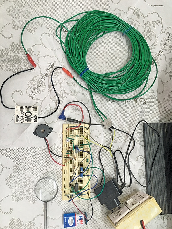
For consistent protection, the sensor leads must remain connected to the main circuit whenever the vehicle is parked. Any disconnection, cutting, or shorting of the wires triggers the alarm and activates the LED indicator. The detector is powered by an external 12V DC adaptor, with a 9V dry cell providing backup during power failures. Fig. 1 displays the author’s prototype of the detector.


Circuit and working
Fig. 2 shows the circuit diagram of the vehicle theft detector. The system is built around quad op-amp LM324 (IC1), quad 2-input NAND gate IC 7400 (IC2), and a few other components.

The quad op-amp IC LM324 (IC1) functions as a voltage comparator. The IC1A comparator detects higher voltage output from the sensor (in the dotted box) when the connecting wires (between TP1 and TP2) are short-circuited or connected while someone attempts to tamper with the vehicle.

The IC1B comparator detects lower voltage when the sensor wires are cut or become open-circuited. Potentiometers VR1 and VR2 provide reference voltages for comparators IC1A and IC1B. Under normal conditions, both comparators produce logic low outputs. However, during voltage disturbances, the output of either comparator becomes logic high and initiate the alarm.
| Parts List |
| Semiconductors: IC1 (IC1A, IC1B, IC1E) – LM324 quad op-amp IC2 (IC2A-IC2E) – 74C00 quad NAND gate T1 – BC547 NPN transistor D1-D7 – 1N4007 rectifier diode LED1 – 5mm LED red colour Resistors (all 1/4-watt, ±5% carbon): Capacitors: Miscellaneous: |
Construction and testing
An actual-size, single-sided PCB layout for the circuit is shown in Fig. 3, and its component layout in Fig. 4. Alternatively, the circuit can be assembled as per Fig. 2 on a multipurpose board.


Once assembled, the mounted board should be enclosed in a suitable enclosure with openings for the buzzer and LED indicator. A PVC electrical box, readily available at low cost, is a good option. The sensor circuit can be soldered onto a strip of multipurpose board with sturdy leads to connect the main circuit wires.
For testing, connect the sensor (within dotted lines in the circuit diagram) to the main circuit PCB. Power the circuit using a 12V DC adaptor and a 9V backup battery.
During calibration
- Adjust potentiometer VR1 to 3.85V and VR2 to 2.25V
• Connect the security wire loop between TP1 and TP2
• Open, short and reverse; ensure buzzer PZ1 and LED1 turn on
• Press push button S1 momentarily to turn off the buzzer and LED after connecting the security loop between TP1 and TP2
• Repeat the tests using a 9V battery, disconnecting the 12V DC adaptor
After satisfactory testing, insulate and seal the sensor circuit in a small tube with epoxy compound, leaving only the thick leads exposed for external connection. The internal circuit of the sensor should not be visible to anyone.
Mount the sensor on the vehicle and connect it to the alarm circuit using a suitable length of weather-resistant twin-core cable. The connection near the vehicle can be done with crocodile clips, an auto wiring plug and socket, or any other connector type, based on user preference.
How it protects your vehicle from theft
The main circuit, including the assembled PCB, should remain inside the house. The vehicle to be protected should be fixed with sensor and twin wire and connected between TP1 and TP2. If someone attempts to steal the vehicle, the wire will break, triggering the buzzer to alert the user.
Caution
The 12V power supply adaptor must be of the mains-isolated type, either step-down transformer and rectifier-based or SMPS type. Non-isolated power supplies with capacitors or resistors for voltage reduction must never be used, as this could lead to electric shock or electrocution when connecting or disconnecting wires to the vehicle sensor.
To ensure trouble-free operation, the connecting wires should be laid carefully so that they are not disturbed by nearby people, children, or animals.
The device has been tested with a 20-metre-long, 1mm dia, single-core cable (two wires), as shown in the photo. However, such a thick cable is unnecessary. It is recommended to use a twin-core copper flat cable (23/0052, 1100V grade).
EFY note. It would be better to assemble D4, D5, R8, D6, and D7 on a zero PCB rather than a PCB shown in Fig. 4. This assembly functions as a sensor. Fix it in the vehicle and connect the two ends of the sensor wires (from the vehicle) to the terminals TP1 and TP2 of the main circuit using two-core long wires.
Modification
If a louder hooter is required, a 12V sugar cube relay with a freewheeling diode can be connected in parallel to the existing buzzer. The hooter can then be connected through the relay’s normally open (NO) contact, powered by the 12V supply.
P. Balasubramanian is a retired scientific officer from the Nuclear Power Corporation of India Ltd (NPCIL). His areas of interest include microcontrollers and power electronics.


![[5G & 2.4G] Indoor/Outdoor Security Camera for Home, Baby/Elder/Dog/Pet Camera with Phone App, Wi-Fi Camera w/Spotlight, Color Night Vision, 2-Way Audio, 24/7, SD/Cloud Storage, Work w/Alexa, 2Pack](https://m.media-amazon.com/images/I/71gzKbvCrrL._AC_SL1500_.jpg)


![[3 Pack] Sport Bands Compatible with Fitbit Charge 5 Bands Women Men, Adjustable Soft Silicone Charge 5 Wristband Strap for Fitbit Charge 5, Large](https://m.media-amazon.com/images/I/61Tqj4Sz2rL._AC_SL1500_.jpg)


