Check out our latest products

![[5G & 2.4G] Indoor/Outdoor Security Camera for Home, Baby/Elder/Dog/Pet Camera with Phone App, Wi-Fi Camera w/Spotlight, Color Night Vision, 2-Way Audio, 24/7, SD/Cloud Storage, Work w/Alexa, 2Pack](https://m.media-amazon.com/images/I/71gzKbvCrrL._AC_SL1500_.jpg)


RGB LED lighting is widely used in home automation, smart lighting, and creative projects. This project demonstrates building an IoT-enabled RGB LED Controller using the IndusBoard Coin V2 and a WS2812B NeoPixel LED ring.
Key Features:
- Web-Based Control – Change colors, adjust brightness, and control individual LEDs.
- Custom Animations – Includes various lighting effects and animation modes.
- Scalable Design – Can be adapted to control long LED strips instead of a circular LED ring.
- Fine-Tuned Control – Adjust brightness and manage individual LEDs for customized effects.
This project is ideal for DIY enthusiasts, IoT developers, and smart home automation projects.
Use Cases
- Smart Home Lighting: Customize RGB lighting in different rooms.
- Interactive Displays: Use NeoPixels for visual effects.
- Wearable Tech: Small-scale RGB control for smart clothing.
- Art Installations: Use animations for aesthetic displays.
Bill Of Material
| Component | Quantity |
| IndusBoard Coin V2 | 1 |
| WS2812B NeoPixel LED Ring/Strip | 1 |
| Power Supply (5V, 2A recommended) | 1 |
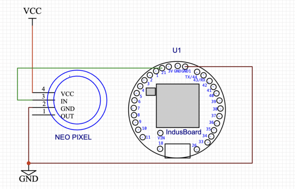
Circuit Design
This project utilizes the IndusBoard Coin V2, which features 30+ GPIO pins, allowing flexibility in choosing the data pin for the WS2812B NeoPixel LEDs. These LEDs are controlled using a single data line, making them easy to manage with the onboard microcontroller.
In this setup, the NeoPixel LED strip’s data pin is connected to pin 21 of the IndusBoard. However, since the IndusBoard has 30+ I/O pins, you can modify this project to control multiple LED strips, effectively covering an entire home with LED lighting. We are building a controller for a single LED strip for this demonstration, but it can always be expanded.
Additionally, the IndusBoard Coin V2 includes a built-in light sensor, which can be integrated into the code for automation features such as day/night detection, automatic brightness adjustment, and light-based on/off control. However, in this project, the light sensor is not utilized.

This setup provides a simple yet powerful foundation for smart LED lighting and can be easily customized for various applications.
Code Explanation
Setting Up the IoT RGB LED Controller
Step 1: Install the Adafruit NeoPixel Library
Before starting, install the Adafruit NeoPixel library in the Arduino IDE. While you can use other libraries, this one is widely used and simplifies the process.
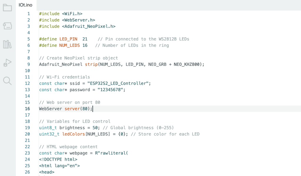
Step 2: Include Necessary Libraries
At the beginning of the code, we include essential libraries:

- WiFi.h – Handles WiFi connectivity.
- WebServer.h – Sets up a simple HTTP web server.
- Adafruit_NeoPixel.h – Controls WS2812B RGB LEDs.
Step 3: Define Pins and LED Configuration
- LED_PIN is assigned GPIO 21.
- NUM_LEDS is set to 16 (for a ring of 16 LEDs).
- The Adafruit_NeoPixel object (
strip) is created for controlling the LEDs.
Step 4: Set Up the Web Server
The ESP32-S2 creates a WiFi Access Point (AP) with the following credentials:
- SSID:
ESP32S2_LED_Controller - Password:
12345678 - A web server is set up on port 80.
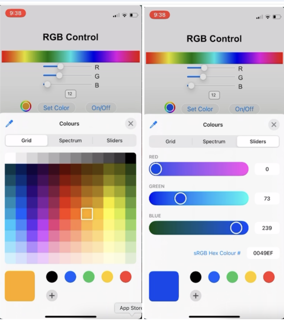
Step 5: Create the Web Page UI & LED Control Functions
The HTML & JavaScript code is embedded to provide a user-friendly interface, allowing users to:
- Adjust RGB colors for individual LEDs.
- Run predefined animations.
- Interact with an LED ring UI.
Step 6: Powering & Connecting the Board
- Power the IndusBoard Coin V2 and connect the LED strip.
- If the LED strip is small, it can be powered directly from the IndusBoard.
- For larger LED strips, use a separate power source and connect only the control line to the IndusBoard.
Step 7: Connecting to the Controller & Using the Web UI
- Open your Wi-Fi settings on your phone.
- Look for the IndusRGB Controller WiFi network.
- Connect using the password 12345678.
- Open a browser and enter
192.168.4.1in the address bar. - Use the web UI to:
- Pick any color from 10+ million colors.
- Adjust brightness.
- Control individual LEDs.
- Run various lighting animations.

![[3 Pack] Sport Bands Compatible with Fitbit Charge 5 Bands Women Men, Adjustable Soft Silicone Charge 5 Wristband Strap for Fitbit Charge 5, Large](https://m.media-amazon.com/images/I/61Tqj4Sz2rL._AC_SL1500_.jpg)