Check out our latest products
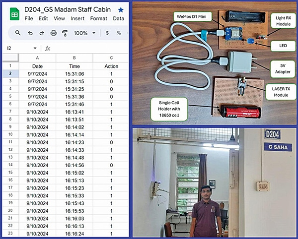
Vigilance of any room, location, or enclosure is always challenging, especially when it cannot be physically locked. A real-life scenario requiring the tracking of intrusions in a monitored space, inspired the creation of this cost-effective solution to log movement onto a Google Sheet using an optical fence.
This concept can be extended to any monitored area like those under CCTV surveillance, where constant attention to the screen is unnecessary.
The Google Sheet tracks the exact date and time of intrusions, enabling to pinpoint specific moments and verify access through CCTV footage. Other potential applications include monitoring corridors, examination rooms, or open pathways where movement needs to be logged.

The goal is not just to count persons but to track the timing of every movement. Additional buzzers or light indicators can enhance the system’s functionality.
| Bill of Materials | |
| Components | Quantity |
| WeMos D1 mini (MOD1) | 1 |
| Laser transmitter | 1 |
| Optical receiver | 1 |
| Jumper wires | 3 |
| 18650 rechargeable batteries (3.7V) | 2 |
| 5V USB cable with adaptor | 1 |
Using a simple laser light sensor setup with the WeMos D1 Mini, this concept comes to life. A 10-second timer updates the Google Sheet every 10 seconds to record inactivity, while activity prompts an immediate update. A new 10-second timer is then initiated after each detection.

Fig. 1 illustrates the proposed setup for the observation zone, with the WeMos D1 Mini and laser light assembly. The required components (bill of materials) are listed in the table.

Features and Technical Specifications of the Laser Module used in the Device
The laser module used in the device is RoHS (restriction of hazardous substances) compliant and cost-effective. Its wavelength ranges from 635nm to 660nm, with a rise and fall time of 0.5ns.
The module is available in two package types: TO-18 (diameter 5.6mm) and TO-5 (diameter 9mm). The operating temperature ranges from -10°C to +40°C, while the storage temperature spans from -15°C to +85°C. The output power (Po) is 5mW, with a normal operating voltage of 2.2V and a maximum operating voltage of 2.7V.
The threshold current values are 15mA (min), 20mA (normal), and 30mA (max), and the operating current ranges from 65mA to 80mA.
The beam angle deviation is approximately +3 degrees for both parallel and perpendicular conditions, and the beam divergence ranges from 8 to 12 degrees (parallel) and 23 to 32 degrees (perpendicular).

A block diagram of the setup is shown in Fig. 2. While the device will operate without an internet connection for actions like triggering a buzzer, but the intrusion data will not be recorded on the Google Sheet without an active connection.
Features and Technical Specifications of the Receiver Module Used
The ISO 203 is a 3-pin sensor, a compact light sensor (receiver) diode with an integrated amplifier and an open-collector transistor at its output. As an open-collector transistor, it requires a pull-up resistor (10kΩ) to ensure the output is collected.
The module operates on a 5V DC power supply, and its output can only go low (L). The open-collector transistor can sink a maximum of 20mA of current.
Circuit and Working
Fig. 3 shows the circuit diagram of the device. The setup is based on the WeMos D1 Mini (MOD1), light sensor receiver (S1), and laser light transmitter. The receiver unit can be powered with a 5V adaptor after uploading the source code, if the 3.7V battery is not used.
The transistor is powered by the 18650 rechargeable battery (3.7V). The internal assembly of the laser light sensor is shown in Fig. 4, while Fig. 5 provides the pin details of the WeMos board.


First, create the Google Sheet and obtain its ID. This can be found in the URL of the Google Sheet, as shown in Fig. 6. Once the sheet ID is noted, proceed to configure the Wi-Fi SSID and password for the local network. Next, configure the URL and Google Sheet ID within the source code.


The sensor data is checked in a continuous loop and updated on the Google Sheet. Fig. 7 shows a snippet of the source code.


Testing
Begin by assembling the components, referring to Figs. 4 and 8 before completing the connections. Ensure the code is uploaded to the ESP8266 chip (WeMos D1 Mini board). Connect the RX and TX (laser receiver and transmitter) circuits as shown in the wiring diagram in Fig. 8.
Once the components are correctly assembled, verify the connections. Power the TX laser device and place the RX device in the line of sight.
Dr Geetali Saha works in the Department of Electronics and Communication, GCET, Anand, Gujarat, and Parth Shah from Component Craft successfully implemented this device.


![[5G & 2.4G] Indoor/Outdoor Security Camera for Home, Baby/Elder/Dog/Pet Camera with Phone App, Wi-Fi Camera w/Spotlight, Color Night Vision, 2-Way Audio, 24/7, SD/Cloud Storage, Work w/Alexa, 2Pack](https://m.media-amazon.com/images/I/71gzKbvCrrL._AC_SL1500_.jpg)


![[3 Pack] Sport Bands Compatible with Fitbit Charge 5 Bands Women Men, Adjustable Soft Silicone Charge 5 Wristband Strap for Fitbit Charge 5, Large](https://m.media-amazon.com/images/I/61Tqj4Sz2rL._AC_SL1500_.jpg)
